
一. 给平行光添加阴影
1. 生成一张深度帧缓存
glwidget.h
    //-----------------测试参数
    QOpenGLFramebufferObject* depthMapFBO;
    const unsigned int SHADOW_WIDTH = 1024, SHADOW_HEIGHT = 1024;
glwidget.cpp
//----------------阴影处理-----------------------------------
	depthMapFBO = new QOpenGLFramebufferObject(	SHADOW_WIDTH,
												SHADOW_HEIGHT,
												QOpenGLFramebufferObject::Depth
											  );
在LearnOpenGL中,使用了glDrawBuffer(GL_NONE);,glReadBuffer(GL_NONE);。但由于QT封装的类QOpenGLFramebufferObject不支持深度贴图的导出(好像无法提取出深度贴图),因此需要使用纹理颜色来代表深度值。故不能使用glDrawBuffer(GL_NONE);,glReadBuffer(GL_NONE);。
若要使用glDrawBuffer(GL_NONE);,glReadBuffer(GL_NONE);,需按如下代码使用:
	QOpenGLFunctions_3_3_Core *core = QOpenGLContext::currentContext()->versionFunctions<QOpenGLFunctions_3_3_Core>();
    core->glDrawBuffer(GL_NONE);
    core->glReadBuffer(GL_NONE);
2. 生成Shadow Mapping
(1)计算平行光源视口下的正交投影矩阵
    QMatrix4x4 lightSpaceMatrix;
    {
        QVector3D lightPos = -scene.dirlight->getDirection().normalized()*50;
        QMatrix4x4 lightProjection, lightView;

        float near_plane = 0.50f, far_plane = 100.5f;
        const float eyeing = 50.0f;
        lightProjection.ortho(-eyeing, eyeing, -eyeing, eyeing, near_plane, far_plane);
        lightView.lookAt(lightPos, QVector3D(0,0,0), QVector3D(0.0, 1.0, 0.0));
        lightSpaceMatrix = lightProjection * lightView;
    }
(2)生成shadow mapping图
    // 生成shadow mapping 图
    glViewport(0, 0, SHADOW_WIDTH, SHADOW_HEIGHT);
    depthMapFBO->bind();
    glEnable(GL_DEPTH_TEST);
    glClearColor(1,0,1,1);
    glClear(GL_COLOR_BUFFER_BIT |GL_DEPTH_BUFFER_BIT);
    simpleDepthShader->bind();//阴影图着色器
    simpleDepthShader->setUniformValue("lightSpaceMatrix",lightSpaceMatrix);

    for(int i=0;i<scene.objects.size();++i){
        simpleDepthShader->setUniformValue("model",scene.objects.at(i)->model.getmodel());
        scene.objects.at(i)->Draw(*simpleDepthShader);
    }
    depthMapFBO->release();
其中:
simpleDepthShader的着色器代码为:
#version 450 core
layout (location = 0) in vec3 position;

uniform mat4 lightSpaceMatrix;
uniform mat4 model;

void main()
{
    gl_Position = lightSpaceMatrix * model * vec4(position, 1.0f);
}
#version 450 core
out vec4 FragColor;
void main()
{
    gl_FragDepth = gl_FragCoord.z;//可注释
    FragColor = vec4(vec3(gl_FragCoord.z), 1.0f);
}
3. 显示阴影图,验证正确性
注意:不要忘记重设glViewport(0,0,width(),height());
// 显示shadow mapp 图
    glViewport(0,0,width(),height());
    glClear(GL_COLOR_BUFFER_BIT | GL_DEPTH_BUFFER_BIT|GL_STENCIL_BUFFER_BIT);
    debug_dep->bind();//shader

	//纹理绑定
    debug_dep->setUniformValue("depthMap",0);
    glActiveTexture(GL_TEXTURE0);
    glBindTexture(GL_TEXTURE_2D,depthMapFBO->texture());

    //渲染
    renderQuad();

    debug_dep->release();
void GLWidget::renderQuad()
{
    float quadVertices[] = {
        // positions        // texture Coords
        -1.0f,  1.0f, 0.0f, 0.0f, 1.0f,
        -1.0f, -1.0f, 0.0f, 0.0f, 0.0f,
         1.0f,  1.0f, 0.0f, 1.0f, 1.0f,
         1.0f, -1.0f, 0.0f, 1.0f, 0.0f,
    };
    // setup plane VAO
    QOpenGLVertexArrayObject quadVAO;
    QOpenGLBuffer quadVBO(QOpenGLBuffer::VertexBuffer);
    quadVAO.create();
    quadVAO.bind();
    quadVBO.create();
    quadVBO.bind();
    quadVBO.allocate(quadVertices,sizeof(quadVertices));
    glEnableVertexAttribArray(0);
    glVertexAttribPointer(0, 3, GL_FLOAT, GL_FALSE, 5 * sizeof(float), (void*)0);
    glEnableVertexAttribArray(1);
    glVertexAttribPointer(1, 2, GL_FLOAT, GL_FALSE, 5 * sizeof(float), (void*)(3 * sizeof(float)));
    glDrawArrays(GL_TRIANGLE_STRIP, 0, 4);
    quadVAO.release();
}
其中着色器为:
#version 450 core
layout (location = 0) in vec3 aPos;
layout (location = 1) in vec2 aTexCoords;

out vec2 TexCoords;

void main()
{
    TexCoords = aTexCoords;
    gl_Position = vec4(aPos, 1.0);
}
#version 450 core
out vec4 FragColor;

in vec2 TexCoords;

uniform sampler2D depthMap;

void main()
{
    float depthValue = texture(depthMap, TexCoords).r;
    FragColor = vec4(vec3(depthValue), 1.0); // orthographic
}
深度图结果
可以发现在阴影图中,地面矩形有一部分深度为白色。猜测可能是前段矩形不在正交投影范围内(因为正交投影与透视投影不同,透视投影更符合人的视觉感官)


二、使用阴影贴图生成阴影
1. 修改着色器
vert新增uniform mat4 lightSpaceMatrix;,out vec4 FragPosLightSpace;
#version 450 core
layout (location = 0) in vec3 aPos;
layout (location = 1) in vec3 aNormal;
layout (location = 2) in vec2 aTexCoords;

out vec3 Normal;
out vec3 FragPos;
out vec2 TexCoords;
out vec4 FragPosLightSpace;

uniform mat4 model;
uniform mat4 view;
uniform mat4 projection;
uniform mat4 lightSpaceMatrix;

void main()
{

        Normal = mat3(transpose(inverse(model))) * aNormal;
        TexCoords = aTexCoords;
        FragPos = vec3(model * vec4(aPos,1.0));
        FragPosLightSpace = lightSpaceMatrix * vec4(FragPos, 1.0);
        gl_Position = projection * view * model * vec4(aPos,1.0);
}
frag新增in vec4 FragPosLightSpace;,uniform sampler2D shadowMap;
新增函数float ShadowCalculation(vec4 fragPosLightSpace);
float ShadowCalculation(vec4 fragPosLightSpace)
{
    // 执行透视除法
    vec3 projCoords = fragPosLightSpace.xyz / fragPosLightSpace.w;
    // 变换到[0,1]的范围
    projCoords = projCoords * 0.5 + 0.5;
    // 取得最近点的深度(使用[0,1]范围下的fragPosLight当坐标)
    float closestDepth = texture(shadowMap, projCoords.xy).r;
    // 取得当前片段在光源视角下的深度
    float currentDepth = projCoords.z;
    // 检查当前片段是否在阴影中
    float shadow = currentDepth > closestDepth  ? 1.0 : 0.0;

    return shadow;
}
在计算平行光光照效果时加入
   // 计算阴影
    float shadow = ShadowCalculation(FragPosLightSpace);
    vec3 lighting = (ambient + (1.0 - shadow) * (diffuse + specular));
总代码为
#version 450 core

struct Material {
    vec3 color;
    float shiness;
};

struct DirLight {
    bool Activated;
    vec3 direction;

    vec3 ambient;
    vec3 diffuse;
    vec3 specular;
};


struct PointLight {
    vec3 position;
    vec3 lightnormal;

    vec3 ambient;
    vec3 diffuse;
    vec3 specular;

    float constant;
    float linear;
    float quadratic;
};

//顶点信息
in vec3 Normal;
in vec3 FragPos;
in vec2 TexCoords;

in vec4 FragPosLightSpace;
uniform sampler2D shadowMap;
//输出
out vec4 FragColor;

//视点
uniform vec3 viewPos;
//平行光
uniform DirLight dirLight;

//点光源
uniform PointLight pointLights[16];
uniform int numPointLights;


uniform Material material;

// function prototypes
vec3 CalcDirLight(DirLight light, vec3 normal, vec3 viewDir);
vec3 CalcPointLight(PointLight light,vec3 normal, vec3 fragPos,vec3 viewDir);
float ShadowCalculation(vec4 fragPosLightSpace);

void main()
{
       // properties
       vec3 norm = normalize(Normal);
       vec3 viewDir = normalize(viewPos - FragPos);//片元点指向视点
       vec3 result = vec3(0,0,0);
       // phase 1: parallel lights
       if(dirLight.Activated){
            result += CalcDirLight(dirLight, norm, viewDir);
       }
       // phase 2: point lights

       for(int i = 0; i < numPointLights; i++){
            result += CalcPointLight(pointLights[i], norm, FragPos, viewDir);
       }
       FragColor = vec4(result,1.0);
}

float ShadowCalculation(vec4 fragPosLightSpace)
{
    // 执行透视除法
    vec3 projCoords = fragPosLightSpace.xyz / fragPosLightSpace.w;
    // 变换到[0,1]的范围
    projCoords = projCoords * 0.5 + 0.5;
    // 取得最近点的深度(使用[0,1]范围下的fragPosLight当坐标)
    float closestDepth = texture(shadowMap, projCoords.xy).r;
    // 取得当前片段在光源视角下的深度
    float currentDepth = projCoords.z;
    // 检查当前片段是否在阴影中
    float shadow = currentDepth > closestDepth  ? 1.0 : 0.0;

    return shadow;
}

//计算平行光源
vec3 CalcDirLight(DirLight light, vec3 normal, vec3 viewDir){
    //平行光反方向
    vec3 lightDir = normalize(-light.direction);
    //计算cos衰减
    float diff = max(dot(lightDir,normal),0.0);

    //反射方向
    vec3 reflectDir = reflect(-lightDir,normal);
    //计算镜面反射系数
    float spec = pow(max(dot(viewDir,reflectDir),0.0),material.shiness);

    vec3 ambient = light.ambient * material.color;
    vec3 diffuse = light.diffuse * diff * material.color;
    vec3 specular = light.specular * spec * material.color;

    // 计算阴影
    float shadow = ShadowCalculation(FragPosLightSpace);
    vec3 lighting = (ambient + (1.0 - shadow) * (diffuse + specular));

    return lighting;
}

//计算点光源
vec3 CalcPointLight(PointLight light,vec3 normal, vec3 fragPos,vec3 viewDir){
    //光源反方向
    vec3 lightDir = normalize(light.position - fragPos);

    float angleDecay = 1.0f;
    if(any(notEqual(light.lightnormal,vec3(0,0,0)))){
        angleDecay = max(dot(-lightDir,normalize(light.lightnormal)),0.0f);
    }
    float diff = max(dot(lightDir,normal),0.0);
    vec3 reflectDir = reflect(-lightDir,normal);
    float spec = pow(max(dot(reflectDir,viewDir),0.0),material.shiness);

    float distance = length(light.position - fragPos);
    float attenuation = 1.0/(light.constant + light.linear * distance + light.quadratic * (distance * distance));

    vec3 ambient = light.ambient * material.color;
    vec3 diffuse = light.diffuse * diff * material.color;
    vec3 specular = light.specular * spec * material.color;

    ambient *= attenuation;
    diffuse *= attenuation;
    specular *= attenuation;

    ambient *= angleDecay;
    diffuse *= angleDecay;
    specular *= angleDecay;

    return (ambient + diffuse + specular);
}
2. 添加阴影
(1)uniform
shaderSelector.getShader(j)->setUniformValue("lightSpaceMatrix",lightSpaceMatrix);
(2)深度图
scene.shaderPrograms[i]->setUniformValue("shadowMap",0);
glActiveTexture(GL_TEXTURE0);
glBindTexture(GL_TEXTURE_2D,depthMapFBO->texture());
3. 结果
可以看到地板四边形渲染出很大一块交替黑线。这种阴影贴图的不真实感叫做阴影失真(Shadow Acne)


三、阴影失真(Shadow Acne)
我们可以用一个叫做 阴影偏移(shadow bias) 的技巧来解决这个问题,我们简单的对表面的深度(或深度贴图)应用一个偏移量,这样片段就不会被错误地认为在表面之下了。
float bias = 0.005;
float shadow = currentDepth - bias > closestDepth  ? 1.0 : 0.0;
一个0.005的偏移就能帮到很大的忙,但是有些表面坡度很大,仍然会产生阴影失真。有一个更加可靠的办法能够根据表面朝向光线的角度更改偏移量:使用点乘:
float bias = max(0.05 * (1.0 - dot(normal, lightDir)), 0.005);
float shadow = currentDepth - bias > closestDepth  ? 1.0 : 0.0;

当光线与法线角度过大时,会出现上方阴影缺失的现象。
四、悬浮
使用阴影偏移的一个缺点是你对物体的实际深度应用了平移。偏移有可能足够大,以至于可以看出阴影相对实际物体位置的偏移。及部分阴影缺失现象。
因为物体看起来轻轻悬浮在表面之上(译注Peter Pan就是童话彼得潘,而panning有平移、悬浮之意,而且彼得潘是个会飞的男孩…)
我们可以使用一个叫技巧解决大部分的Peter panning问题:当渲染深度贴图时候使用正面剔除(front face culling)你也许记得在面剔除教程中OpenGL默认是背面剔除。我们要告诉OpenGL我们要剔除正面。
因为我们只需要深度贴图的深度值,对于实体物体无论我们用它们的正面还是背面都没问题。使用背面深度不会有错误,因为阴影在物体内部有错误我们也看不见。
glCullFace(GL_FRONT);
RenderSceneToDepthMap();
glCullFace(GL_BACK); // 不要忘记设回原先的culling face
注意这里必须是实体物体,否则阴影不会被正确计算
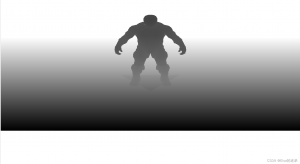
如下图:人物阴影存在,但三角形阴影不存在(因为三角形是单面)

看人物阴影,可以看到当光线角度变大时,阴影也能正确显示。

还有问题:自阴影问题,在显示时会存在较大问题存在。


五、采样过多
光的视锥不可见的区域一律被认为是处于阴影中。
出现这个状况是因为超出光的视锥的投影坐标比1.0大,这样采样的深度纹理就会超出他默认的0到1的范围。
1. 处理上下左右之外阴影
scene.shaderPrograms[i]->setUniformValue("shadowMap",0);
            glActiveTexture(GL_TEXTURE0);
            glBindTexture(GL_TEXTURE_2D,depthMapFBO->texture());
            glTexParameteri(GL_TEXTURE_2D, GL_TEXTURE_MIN_FILTER, GL_NEAREST);
            glTexParameteri(GL_TEXTURE_2D, GL_TEXTURE_MAG_FILTER, GL_NEAREST);
            glTexParameteri(GL_TEXTURE_2D, GL_TEXTURE_WRAP_S, GL_CLAMP_TO_BORDER);
            glTexParameteri(GL_TEXTURE_2D, GL_TEXTURE_WRAP_T, GL_CLAMP_TO_BORDER);
            GLfloat borderColor[] = { 1.0, 1.0, 1.0, 1.0 };
            glTexParameterfv(GL_TEXTURE_2D, GL_TEXTURE_BORDER_COLOR, borderColor);
2. 处理坐标超出了光的正交视锥的远平面阴影
添加if(projCoords.z > 1.0) shadow = 0.0;
float ShadowCalculation(vec4 fragPosLightSpace)
{
    // 执行透视除法
    vec3 projCoords = fragPosLightSpace.xyz / fragPosLightSpace.w;
    // 变换到[0,1]的范围
    projCoords = projCoords * 0.5 + 0.5;
    // 取得最近点的深度(使用[0,1]范围下的fragPosLight当坐标)
    float closestDepth = texture(shadowMap, projCoords.xy).r;
    // 取得当前片段在光源视角下的深度
    float currentDepth = projCoords.z;
    // 检查当前片段是否在阴影中
    float bias = max(0.05 * (1.0 - dot(Normal, -dirLight.direction)), 0.005);
    float shadow = currentDepth - bias > closestDepth  ? 1.0 : 0.0;

    if(projCoords.z > 1.0)
        shadow = 0.0;

    return shadow;
}
运行结果:

这些结果意味着,只有在深度贴图范围以内的被投影的fragment坐标才有阴影,所以任何超出范围的都将会没有阴影。由于在游戏中通常这只发生在远处,就会比我们之前的那个明显的黑色区域效果更真实。
六、PCF降低锯齿块
阴影锯齿如下

修改frag,多次采用深度贴图得到柔和阴影
float shadow = 0.0;
vec2 texelSize = 1.0 / textureSize(shadowMap, 0);
for(int x = -1; x <= 1; ++x)
{
    for(int y = -1; y <= 1; ++y)
    {
        float pcfDepth = texture(shadowMap, projCoords.xy + vec2(x, y) * texelSize).r;
        shadow += currentDepth - bias > pcfDepth ? 1.0 : 0.0;
    }
}
shadow /= 9.0;
这个textureSize返回一个给定采样器纹理的0级mipmap的vec2类型的宽和高。用1除以它返回一个单独纹理像素的大小,我们用以对纹理坐标进行偏移,确保每个新样本,来自不同的深度值。这里我们采样得到9个值,它们在投影坐标的x和y值的周围,为阴影阻挡进行测试,并最终通过样本的总数目将结果平均化。


![[转]我国CAD软件产业亟待研究现状采取对策-卡核](https://www.caxkernel.com/wp-content/uploads/2024/07/frc-f080b20a9340c1a89c731029cb163f6a-212x300.png)