
0.前言
最近在研究OpenFOAM自带的网格生成软件——snappyHexMesh,并准备拿圆柱绕流算例试试手。主要参考:京东手机的博客和刘楚云知乎的文章。在他们的基础上,学习不同参数对最后网格的影响,并记录下过程。
1.创建圆柱的stl文件
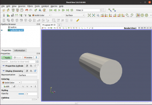
这里用到三维建模软件UG NX6.0。之前用AutoCAD,生成的stl文件的XYZ坐标都会自动拨到正值,这在CFD里是比较麻烦的,所以改用UG。这里忽略画的过程。将stl文件放到OpenFOAM算例的文件夹里,用paraview打开:

2.用AutoSurfacePatch识别不同表面
UG输出的stl文件只带一个表面,所以输入以下指令:
AutoSurfacePatch cylinderug.stl cylinder.stl 130
这里cylinderug.stl是UG输出的stl文件,而后者则是输出的文件。130代表面单元之间超过130度则会被识别成两个面。
输入cat cylinder.stl会看到输出的stl被分成三个patch:
![图片[1]-OpenFOAM自带网格软件——基于snappyHexMesh的圆柱网格画法-卡核](http://www.caxkernel.com/wp-content/uploads/2022/09/20220903015716-6312b47cdd820.png)


又法向量可知,patch0是顶面,patch1是圆柱的侧面,而patch2则是圆柱的底面。这个信息后面会用到。不同的建模画法可能会导致这些patch的顺序不一样,需要注意。
3.必要文档的准备
在OpenFOAM的tutorials文件夹内搜snappyHexMeshDict即可找到模板,我们稍微修改一下就能用。除此之外还需要meshQualityDict和surfaceFeatureExtractDict两个文档。将3个文档复制到system文件夹中。

4.提取stl的特征
将刚刚得到的cylinder.stl放到constant/triSurface中(没有triSurface就创建一个)。并将system/surfaceFeatureExtractDict中的***.stl改成cylinder.stl,如下:

保存退出,然后输入代码:
surfaceFeatureExtract
5.背景网格
用blockMesh画一个背景网格:

需要将圆柱包含在内。这个比较基础就不细讲了。
6.修改snappyhexmeshdict
下面是我修改的snappyHexMeshDict,对一下哪里需要修改:
/*--------------------------------*- C++ -*----------------------------------*\\
  =========                 |
  \\\\      /  F ield         | OpenFOAM: The Open Source CFD Toolbox
   \\\\    /   O peration     | Website:  https://openfoam.org
    \\\\  /    A nd           | Version:  7
     \\\\/     M anipulation  |
\\*---------------------------------------------------------------------------*/
FoamFile
{
    version     2.0;
    format      ascii;
    class       dictionary;
    object      snappyHexMeshDict;
}

// * * * * * * * * * * * * * * * * * * * * * * * * * * * * * * * * * * * * * //

// Which of the steps to run
castellatedMesh true;
snap            true;
addLayers       true;


// Geometry. Definition of all surfaces. All surfaces are of class
// searchableSurface.
// Surfaces are used
// - to specify refinement for any mesh cell intersecting it
// - to specify refinement for any mesh cell inside/outside/near
// - to 'snap' the mesh boundary to the surface
geometry
{
    cylinder.stl
    {
        type triSurfaceMesh;
        name inner_cylinder;

    	regions
    	{
    		patch0          // STL文件中的表面名称
    		{
    		    name surface0;//z=-0.157 surface
    		}
    		patch1
    		{
    		    name cylinder;// 定义圆柱体侧表面为cylinder,这样其他的文件不用改。
    		}
    		patch2
    		{
    		    name surface2;//z=0.157 surface
    		}
    	}
    }
    //- Refine a bit extra around the small centre hole
    refinementBox
    {
        type searchableBox;
        min (-0.2 -0.2 0);
        max (1.2 0.2 0.314);
    }
};


// Settings for the castellatedMesh generation.
castellatedMeshControls
{

    // Refinement parameters
    // ~~~~~~~~~~~~~~~~~~~~~

    // If local number of cells is >= maxLocalCells on any processor
    // switches from from refinement followed by balancing
    // (current method) to (weighted) balancing before refinement.
    maxLocalCells 100000;

    // Overall cell limit (approximately). Refinement will stop immediately
    // upon reaching this number so a refinement level might not complete.
    // Note that this is the number of cells before removing the part which
    // is not 'visible' from the keepPoint. The final number of cells might
    // actually be a lot less.
    maxGlobalCells 2000000;

    // The surface refinement loop might spend lots of iterations refining just a
    // few cells. This setting will cause refinement to stop if <= minimumRefine
    // are selected for refinement. Note: it will at least do one iteration
    // (unless the number of cells to refine is 0)
    minRefinementCells 0;

    // Number of buffer layers between different levels.
    // 1 means normal 2:1 refinement restriction, larger means slower
    // refinement.
    nCellsBetweenLevels 2;


    // Explicit feature edge refinement
    // ~~~~~~~~~~~~~~~~~~~~~~~~~~~~~~~~

    // Specifies a level for any cell intersected by its edges.
    // This is a featureEdgeMesh, read from constant/triSurface for now.
    features
    (
        {
            file "cylinder.eMesh";
            level 0;
        }
    );


    // Surface based refinement
    // ~~~~~~~~~~~~~~~~~~~~~~~~

    // Specifies two levels for every surface. The first is the minimum level,
    // every cell intersecting a surface gets refined up to the minimum level.
    // The second level is the maximum level. Cells that 'see' multiple
    // intersections where the intersections make an
    // angle > resolveFeatureAngle get refined up to the maximum level.


     refinementSurfaces//细化表面
     {
         inner_cylinder//与上面的name对应
         {
             level (2 2);//表面网格细化的最小和最大等级,即网格被分割的最小和最大次数。
             regions//局部细化
             {
                 patch1
                 {
                     level (2 4);
                     patchInfo//patch信息
                     {
                         type wall;//类型只能为wall或者patch
                     }
                 }
                 patch0//patch1和patch2在生成外部网格时会被去除,可以不用定义。
                 {
                     level (2 2);
                     patchInfo
                     {
                         type patch;
                     }
                 }
                 patch2
                 {
                     level (2 2);
                     patchInfo
                     {
                         type patch;
                     }
                 }
             }
         }
     }
    resolveFeatureAngle 30;


    // Region-wise refinement
    // ~~~~~~~~~~~~~~~~~~~~~~

    // Specifies refinement level for cells in relation to a surface. One of
    // three modes
    // - distance. 'levels' specifies per distance to the surface the
    //   wanted refinement level. The distances need to be specified in
    //   descending order.
    // - inside. 'levels' is only one entry and only the level is used. All
    //   cells inside the surface get refined up to the level. The surface
    //   needs to be closed for this to be possible.
    // - outside. Same but cells outside.
     refinementRegions
     {
         refinementBox
         {
             mode inside;
             levels ((1E15 1));
         }
     }


    // Mesh selection
    // ~~~~~~~~~~~~~~

    // After refinement patches get added for all refinementSurfaces and
    // all cells intersecting the surfaces get put into these patches. The
    // section reachable from the locationInMesh is kept.
    // NOTE: This point should never be on a face, always inside a cell, even
    // after refinement.
    // This is an outside point locationInMesh (-0.033 -0.033 0.0033);
    locationInMesh (0.1 0 0.157); // Inside point

    // Whether any faceZones (as specified in the refinementSurfaces)
    // are only on the boundary of corresponding cellZones or also allow
    // free-standing zone faces. Not used if there are no faceZones.
    allowFreeStandingZoneFaces true;
}


// Settings for the snapping.
snapControls
{
    //- Number of patch smoothing iterations before finding correspondence
    //  to surface
    nSmoothPatch 3;

    //- Relative distance for points to be attracted by surface feature point
    //  or edge. True distance is this factor times local
    //  maximum edge length.
    tolerance 1.0;

    //- Number of mesh displacement relaxation iterations.
    nSolveIter 300;

    //- Maximum number of snapping relaxation iterations. Should stop
    //  before upon reaching a correct mesh.
    nRelaxIter 5;

    // Feature snapping

        //- Number of feature edge snapping iterations.
        //  Leave out altogether to disable.
        nFeatureSnapIter 10;

        //- Detect (geometric) features by sampling the surface
        implicitFeatureSnap false;

        //- Use castellatedMeshControls::features
        explicitFeatureSnap true;

        //- Detect features between multiple surfaces
        //  (only for explicitFeatureSnap, default = false)
        multiRegionFeatureSnap true;
}


// Settings for the layer addition.
addLayersControls
{
    // Are the thickness parameters below relative to the undistorted
    // size of the refined cell outside layer (true) or absolute sizes (false).
    relativeSizes true;

    // Per final patch (so not geometry!) the layer information
    layers
    {
        "cylinder.*"
        {
            nSurfaceLayers 3;
        }
    }

    // Expansion factor for layer mesh
    expansionRatio 1.0;


    // Wanted thickness of final added cell layer. If multiple layers
    // is the thickness of the layer furthest away from the wall.
    // Relative to undistorted size of cell outside layer.
    // See relativeSizes parameter.
    finalLayerThickness 0.3;

    // Minimum thickness of cell layer. If for any reason layer
    // cannot be above minThickness do not add layer.
    // See relativeSizes parameter.
    minThickness 0.25;

    // If points get not extruded do nGrow layers of connected faces that are
    // also not grown. This helps convergence of the layer addition process
    // close to features.
    nGrow 0;


    // Advanced settings

    // When not to extrude surface. 0 is flat surface, 90 is when two faces
    // are perpendicular
    featureAngle 30;

    // Maximum number of snapping relaxation iterations. Should stop
    // before upon reaching a correct mesh.
    nRelaxIter 5;

    // Number of smoothing iterations of surface normals
    nSmoothSurfaceNormals 1;

    // Number of smoothing iterations of interior mesh movement direction
    nSmoothNormals 3;

    // Smooth layer thickness over surface patches
    nSmoothThickness 10;

    // Stop layer growth on highly warped cells
    maxFaceThicknessRatio 0.5;

    // Reduce layer growth where ratio thickness to medial
    // distance is large
    maxThicknessToMedialRatio 0.3;

    // Angle used to pick up medial axis points
    minMedianAxisAngle 90;

    // Create buffer region for new layer terminations
    nBufferCellsNoExtrude 0;


    // Overall max number of layer addition iterations. The mesher will exit
    // if it reaches this number of iterations; possibly with an illegal
    // mesh.
    nLayerIter 50;

    // Max number of iterations after which relaxed meshQuality controls
    // get used. Up to nRelaxIter it uses the settings in meshQualityControls,
    // after nRelaxIter it uses the values in meshQualityControls::relaxed.
    nRelaxedIter 20;
}


// Generic mesh quality settings. At any undoable phase these determine
// where to undo.
meshQualityControls
{
    #include "meshQualityDict"

    // Optional : some meshing phases allow usage of relaxed rules.
    // See e.g. addLayersControls::nRelaxedIter.
    relaxed
    {
        //- Maximum non-orthogonality allowed. Set to 180 to disable.
        maxNonOrtho 75;
    }
}


// Advanced

// Write flags
writeFlags
(
    scalarLevels    // write volScalarField with cellLevel for postprocessing
    layerSets       // write cellSets, faceSets of faces in layer
    layerFields     // write volScalarField for layer coverage
);


// Merge tolerance. Is fraction of overall bounding box of initial mesh.
// Note: the write tolerance needs to be higher than this.
mergeTolerance 1E-6;


// ************************************************************************* //
最后终端运行:
snappyHexMesh
运行结束后会生成几个时间步的文件夹:

我们打开paraview查看网格:

我们在实际计算的时候,将时间步里面的polyMesh文件夹放到constant内,覆盖原来的,就可以参加计算了。
网格质量的好坏决定了仿真结果是否准确有效。在snappyHexMeshDict中有许多需要调节的参数,将在后面的博客中记录。


![[转]我国CAD软件产业亟待研究现状采取对策-卡核](https://www.caxkernel.com/wp-content/uploads/2024/07/frc-f080b20a9340c1a89c731029cb163f6a-212x300.png)